Blue Friday patch – about T-Track x4
Let’s explore a structure build around T-Track x4 block in few steps. Download link for rack files and video showing final result can be found at the end of the post.
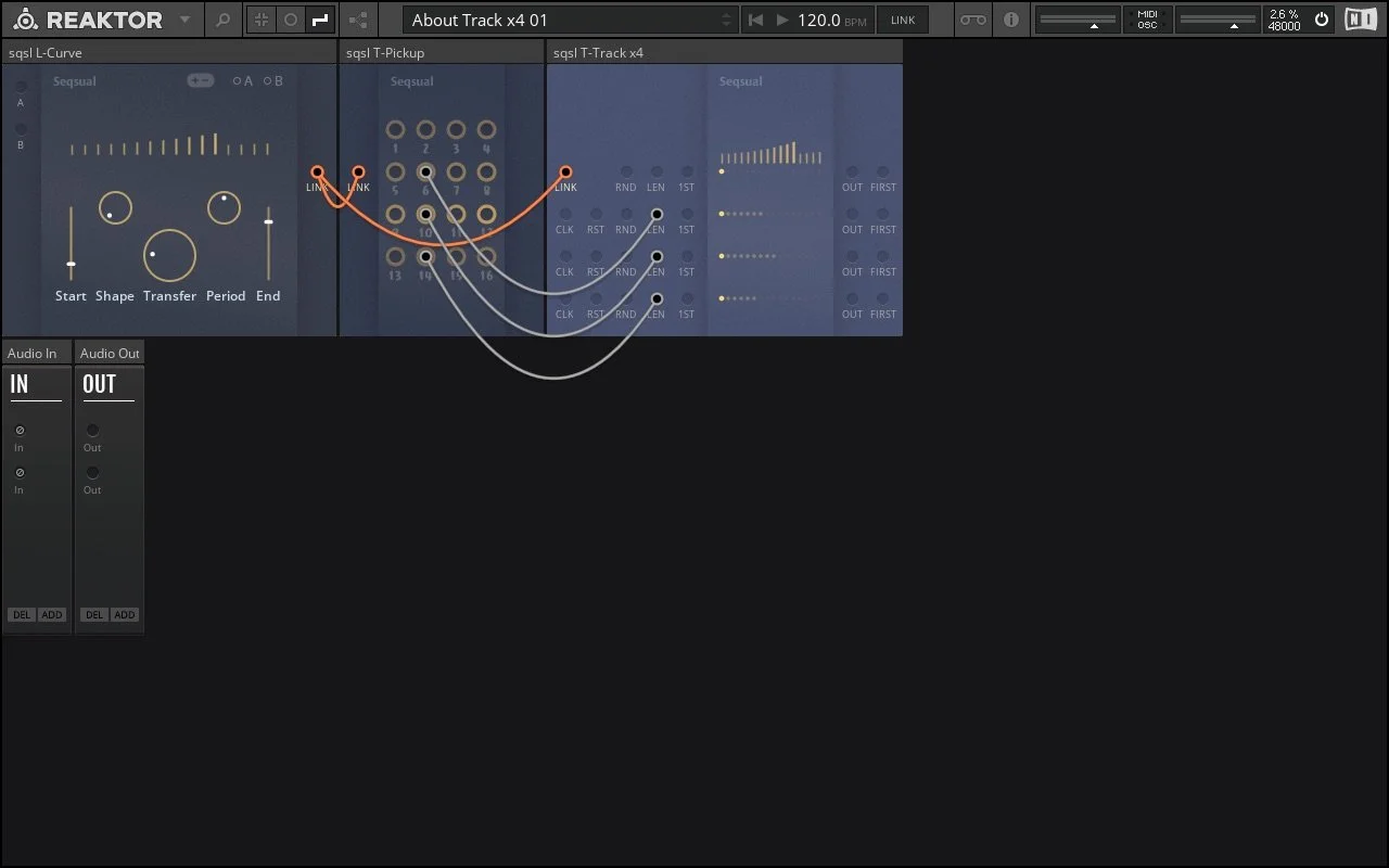
Rack 01 – Link signal explained
T-Track x4 is sequencing module with 4 lines/tracks. Each line has own inputs for clock, for sequence length (LEN) and start point (1ST) but all 4 lines share the same sequence values represented by vertical bars on the panel. Sequence values are read from Link connection (orange color).
In contrast to typical modular analogue CV signals where usually 1 cable is carrying 1 value, a single Link connection in Blue Set contains 16 values. Sequencing patches made with Blue Set will typically have blocks interconnected using Link connection in order to:
generate/set 16 values (blocks with L- prefix; eg: L-Source, L-Curve, L-Sliders…);
process them (P- prefix; eg: P-Shuffle, P-Range, P-Sort, etc…);
access/sequence them (T- prefix; eg: T-Track S, T-Pickup, T-Address…).
Except P-Readout, all blocks with Link input generate random set of values if no valid Link signal is connected to their LINK input.
In the first rack we have L-Curve block as our starting point generating Link signal. Values are calculated as transiiton between 2 edge levels, set by Start and End sliders. Overal shape can be altered by Shape and Period controls and Transfer knobs gradually exchange the start and end point.
Link signal originating from L-Curve is directly accessed – picked up by T-Pickup block where each value has its own output.
In our patch, levels picked up from 6th, 10th and 14th position are controlling length of sequence lines of T-Track x4 – represented by brighter dots (horizontally aligned with the input on the panel). At this point there is no clock signal connected to T-Track x4 so nothing is yet happening but we can move the controls on L-Curve and observe how the generated values are affecting:
sequence lengths (brighter dots) and at the same time;
values that T-Tracks x4 will be advancing through (vertical bars above the dots).
Eventually we can connect some more outputs from T-Pickup to 1ST inputs on T-Tracks x4 to affect also the starting points of the sequence lines.
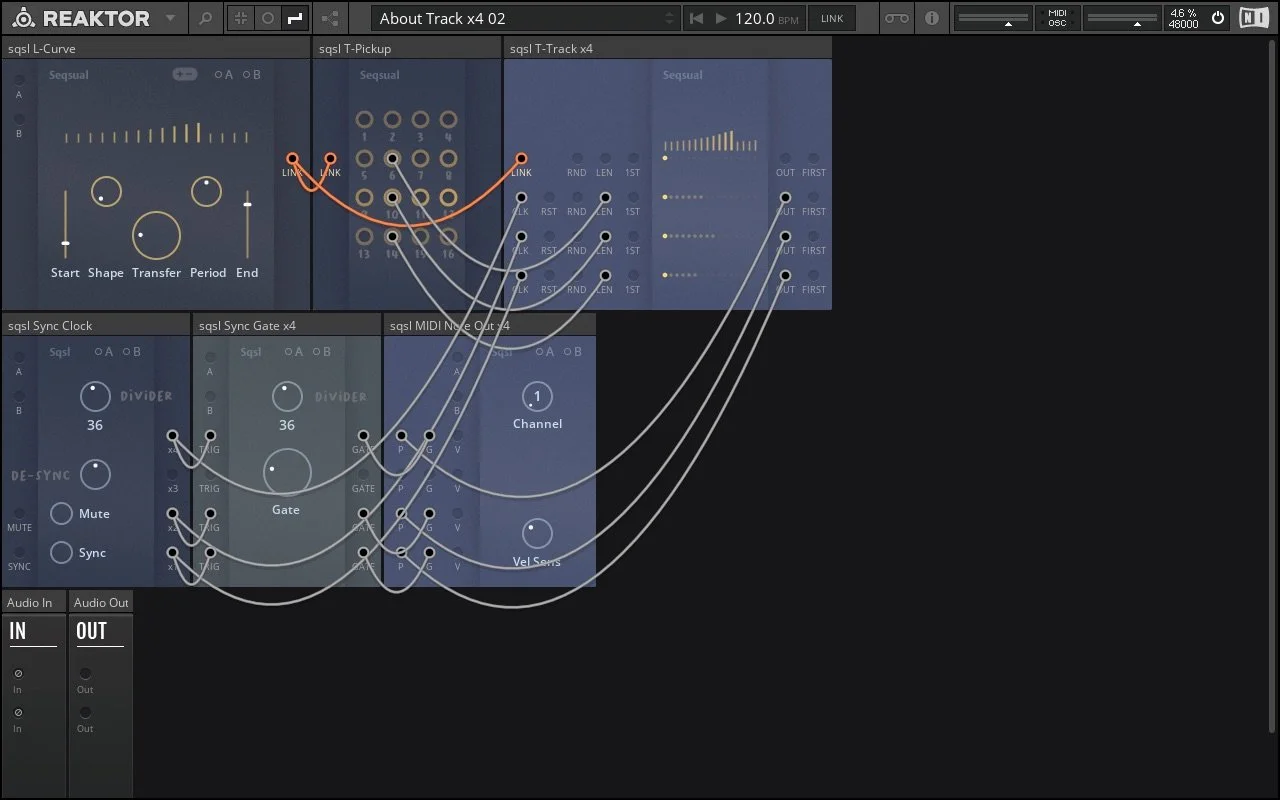
Rack 02 – adding clock and MIDI notes
Each sequence line of T-Track x4 has its own clocking inputs*:
CLK: trigger advance the position (negative trigger advance the position in reverse direction);
RND: trigger sequence to jump to random poisition;
RST: trigger causes.
*CLK and RST inputs are omitted for the first/upper line – it can only be used for random jumps.
Divisions of clock signal from Sync Clock are connected to CLK inputs on T-Track x4 so sequence lines are advancing at different tempos/rythms. They all share same step values (Link) but can have different length and starting points.
Values sent out from the 3 sequence lines are used as pitch information for MIDI notes generated by MIDI Note Out x4 block. Corresponding gates are generated by Sync Gate x4.
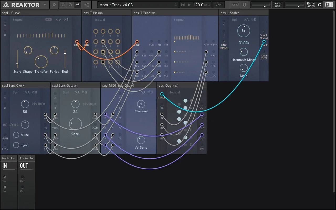
Rack 03 – adding quantizer
We have insterted Quant x4 block between T-Track x4 outputs and MIDI Note Out x4. Signals coming from our 3 sequencing lines are now quantized – fit to scale. To select which scale should be used, we connect L-Scales block to SCALE input of the quantizer (blue connection).
Scale signal/connection sent from L-Scale block is in fact a pre-defined Link signal – containing 16 values, first 12 being used as on/off information for 12 keys (C, C#, D, etc). As Link and Scale signals are compatible, we can connect Scale signal to T-Track’s LINK input or connect Link signal from L-Curve to SCALE input on Quant x4 block for some unusual scales. Consequenctly, Link processing blocks – for example P-Shuffle or P-Range – can be used to manipulate Scale signals/scale definitions.

Rack 04 – sequencing velocity
We have added one more T-Track x4 block. Lenghts of its sequence lines are set by values received from T-Pickup and positions are advanced by the clock divisions from Sync Clock (same as the T-Track in the upper row). There is no signal connected to its LINK input so 16 random step values are generated when the patch is loaded. Output signals are connected to VEL inputs on MIDI Note Out x4 block – adjusting the velocity of outgoing notes. We can use Vel Sens (velocity sensitivity) knob to adjust the amount of effect of incoming signals on final velocity.
At this point we have a playable patch. Adjusting a signle knob – for example Transfer – results in sequences of different lenghts, values, etc. As we have also connected Link signal coming from L-Curve to MASK input of L-Scales block, changing parameters on L-Curve affect selection of active keys in the scale used for quantizing.

Rack 05 – auto-modulation
Two more blocks in the patch – T-Position S and Segment.
T-Position S is acting as random trigger source – every time T-Track’s second line loops (FIRST output) trigger is sent to T-Position’s RND input. When third position is selected, incoming trigger is sent out through output in the front panel (3) to reset the Segment block (RST input) and to advance first sequence line on T-Track x4 below to random position (RND input).
Segment blocks is a sort of single stage envelope – it transition between edge values set by Start and End. Duration of transition is defined by Time control and transition is triggered by reseting the block using Reset button or one of the RST trigger inputs.
In our patch, Segment’s output is modulating Transfer parameter of L-Curve block (B modulation input). At the same time, Segment’s Time parameter is being modulated by the value coming from randomly jumping first line of botom T-Track x4.