Cube sequencer – how does nature counts to 8?
In this post we will have a look at how platonic sequencer (cube) works. We will build the patch in 4 steps – starting from essentials and adding functionality progressively. Rack files of each step are available for download at the bottom of this page.
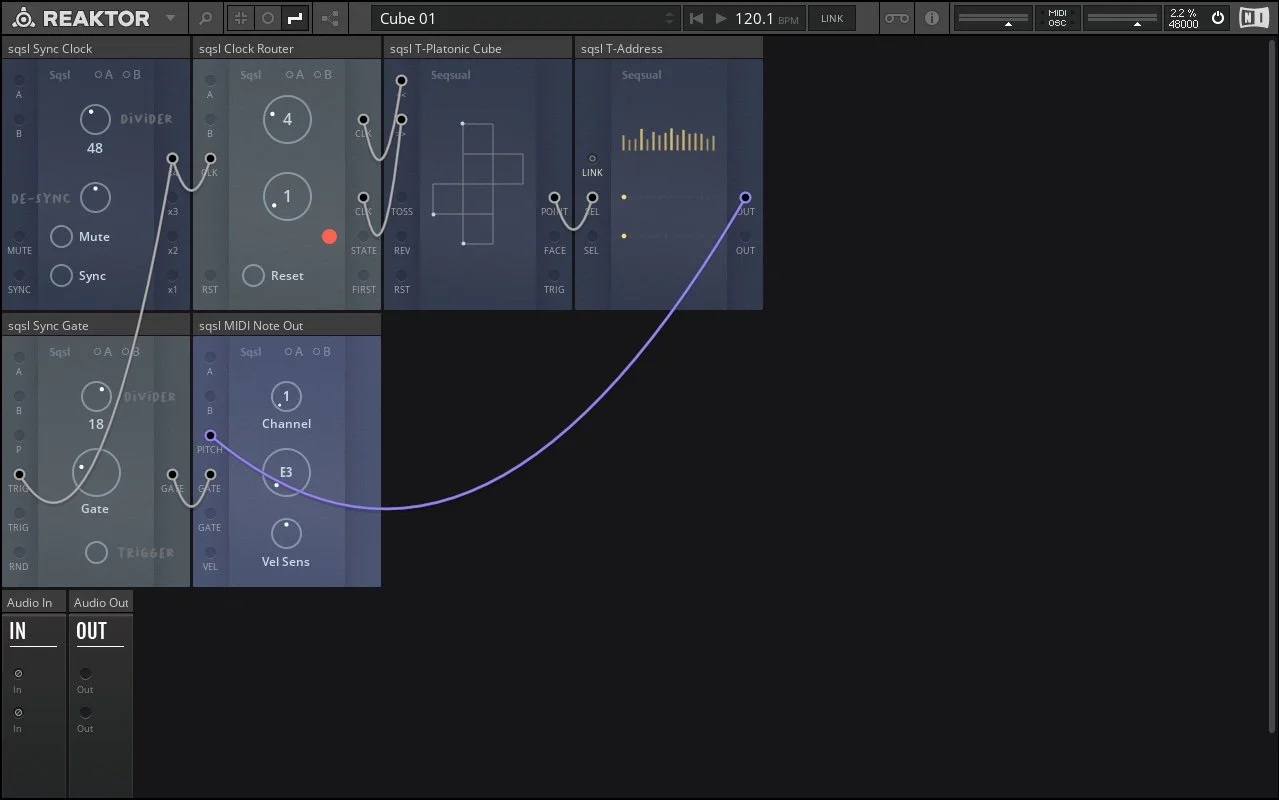
Rack Cube 01
Sync Clock block is a synchronised clock/pulse signal source. It follows Reaktor’s BPM and transport status (play/stop). Reaktor/Reaktor Player can be synchronised to external MIDI clock or Ableton Link. There are 4 simultaneous outputs from Sync Clock – duration between pulses is four times shorter from x4 output than from x1 output, three times shorter from x3 output and two times shorter from x2 output.
Clock signal from x4 output is connected to input of Clock Router block where triggers are split into two outputs. Upper knob controls how many triggers are sent to upper output before switching to lower output. Number of triggers sent out through lower output is defined by lower knob.
Trigger signals from Clock Router are connected to << and >> inputs of T-Platonic Cube.
T-Platonic Cube let us move from point to point around the edges of 3-dimensional object (cube) based on received clock signal. Shape represented visually on the panel is unfolded cube – if we would cut out this shape from paper and fold it, we would get cube object. Current point/position is indicated by bright dot. Several dots can light up at once but they always represent only one point on 3 dimensional cube object.
In case of cube, every point has 3 possible directions where to move. If we exclude reverse direction, we have option to go left or right (considering that ”where we come from” is always behind our back). Every direction has its separate clock input - if we send triggers only to << input, we progress always right and the sequence is a loop of 4 points (one side of cube). If we send every second trigger to >> input, we will ”zig-zag” around the cube. Different combination of left/right received triggers will result in various progressions through cube’s 8 points. If trigger arrives to several inputs at once, lower input has priority (excluding reset).
Every point/position of T-Platonic Cube has a fixed value attached to it - index. First point has index 0/32, second 1/32, third 2/32 etc… Current point’s index is sent to POINT output.
Unique index values are attached to all faces/sides of our cube. Three most recently accessed points define current face and its index value is sent to FACE output. When new face (new side) of the cube is accessed, trigger pulse is sent out from TRIG output.
In our patch, point index (POINT output) is sent to T-Address block’s SEL (select). T-Address block is assigning to every index new value that it has received through LINK connection*. Values are represented as vertical bars and current position (which value is sent to output) is represented as bright dot. There are two separate channels on T-Address aligned horizontally: SEL -> dot indicator of current position -> OUT.
*As nothing is connected to LINK input in this first patch, random values are generated by T-Address block when the patch is loaded. They can be re-generated by clicking on Seqsual logo in the upper left corner of the block’s panel.
T-Address block connected to T-Platonic Cube allows us to move through values defined in Link connection as if the values were placed on the corners of a cube and we were only allowed to move following cube object’s edges. Because cube has 8 points/corners, we will be moving through first 8 values in LINK connection.
MIDI Note Out is generating MIDI note messages from received pitch and gate information. In this patch, it is receiving pitch from T-Address (purple) and gates from Sync Gate block located next to it. Sync Gate is receiving triggers from the same output as Clock Router – resulting in continuous stream of gates being sent to MIDI Note Out.
We have a simple structure going through random notes (spanning 10 octaves) following cube’s geometry.

Rack Cube 02
Let’s extend the first patch by adding L-Sliders, L-Scale and P-Readout block.
L-Sliders allows us ”manually” set 16 values that are all sent out through single LINK connection (orange). P-Readout quantizes to scale and numerically displays values that it is receiving through LINK (from L-Sliders). Lower/grey numbers represent octaves and upper/yellow numbers represent degree position within scale. We can preciselly set desired notes (octaves and degrees) by adjusting the Sliders and reading the numbers on P-Readout. P-Readout works with scale information that it receives through its SCALE input (blue).
If the scale information is updated (eg. root note), quantised values will be adjusted so that the octave/degree positions are preserved (!).
L-Scales block is a library of pre-defined scales - big knob defines root note and two other knobs define scale type (middle knob) and bank (lower knob).
At this stage we have a structure following cube’s geometry and we are able to set the scale and degrees that are used.
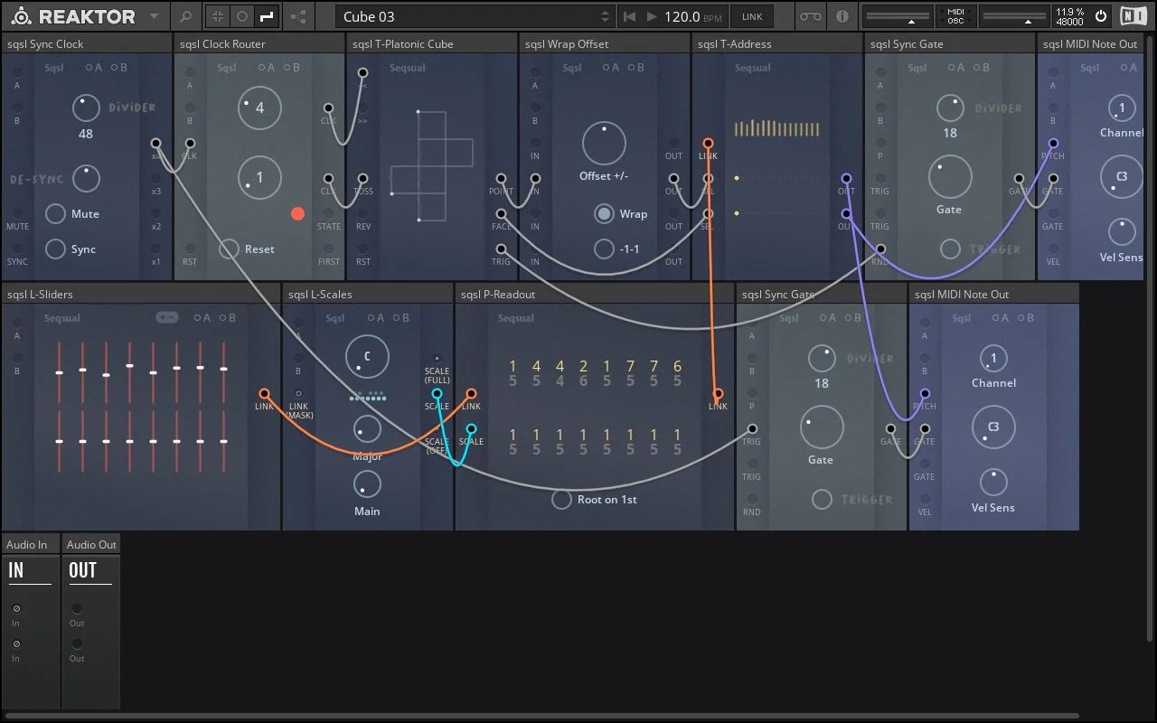
Rack Cube 03
We have added another 3 blocks: Wrap Offset, Sync Gate and MIDI Note Out.
Cube object has 8 points/corners. Cube sequencer travels through 8 different points – POINT output value (index) is between 0/32 and 7/32 – corresponding to positions 1 to 8 in Link signal (which has 16 positions in total). We can use Wrap Offset to control which part of 16 Link positions we are accessing in T-Address. In this cass, index from POINT output is passing through Wrap Offset before being sent to SEL input on T-Address block. By adjusting the Offset +/- knob, we can control which part of Link values is accessed. If no offset is applied, we are accessing positions 1-8.
Similarly, cube has 6 faces so index from FACE output will be in the range 0/32 - 5/32 (positions 1-6 in Link). In this patch the FACE output is connected directly to T-Address so no offset is applied – we are only using first six positions in Link connection (values from first six sliders on L-Sliders block).
Pitch coming from lower T-Address output is derived from face position of cube sequencer and is sent to second MIDI Note Out block (purple). The gates used for those notes are generated by Sync Gate block which is receiving trigger pulse every time face position is changed on cube sequencer (TRIG output on T-Platonic Cube block). As the trigger pulse is sent to RND input of Sync Gate block, gate length is random (with maximum length affected by Divider control).
At this stage we have a two-voice structure following cube’s geometry, we are able to set the scale and degrees that are used. By manually adjusting L-Sliders, Clock Router and Wrap Offset settings we can create variation/develop the patch.
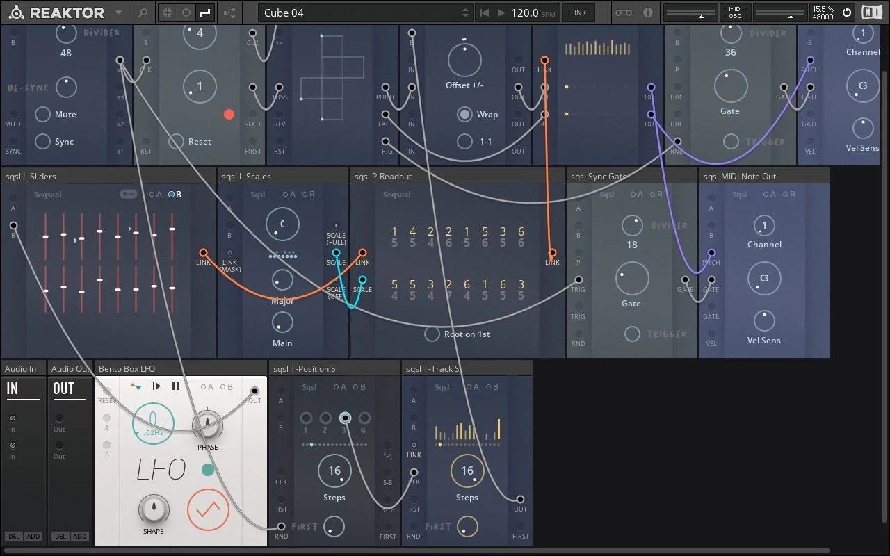
Rack Cube 04
More blocks added: Bento Box LFO, T-Position S and T-Track S.
The job of Bento Box LFO is to slowly adjust/modulate two sliders on L-Sliders block (through B modulation input), so two of the notes in our set of 16 are slowly changing.
T-Position S is used here as random trigger source. It is receiving steady clock signal (from Sync Clock) at its RND input – position is randomly selected for every pulse. When position 3 is selected, trigger is sent out to advance T-Tracks S. As range of T-Position is set to 16 steps, probability of trigger being sent out is 1/16.
T-Track S has nothing connected to its LINK input so values it is going through are generated randomly (represented by vertical bars). Currently selected value is sent to modulate Offset knob on Wrap Offset block - shifting the range of notes that POINT output of cube sequencer is traveling through.
At this final stage, we applied some random modulation so the patch develops automatically.

Each of the 5 platonic solid has its own block in Blue Set. T-Platonic Cube block can be replaced in this patch by any other T-Platonic block as they all follow the same principle/connection logic.