P-Crossfade as source of notes and modulation
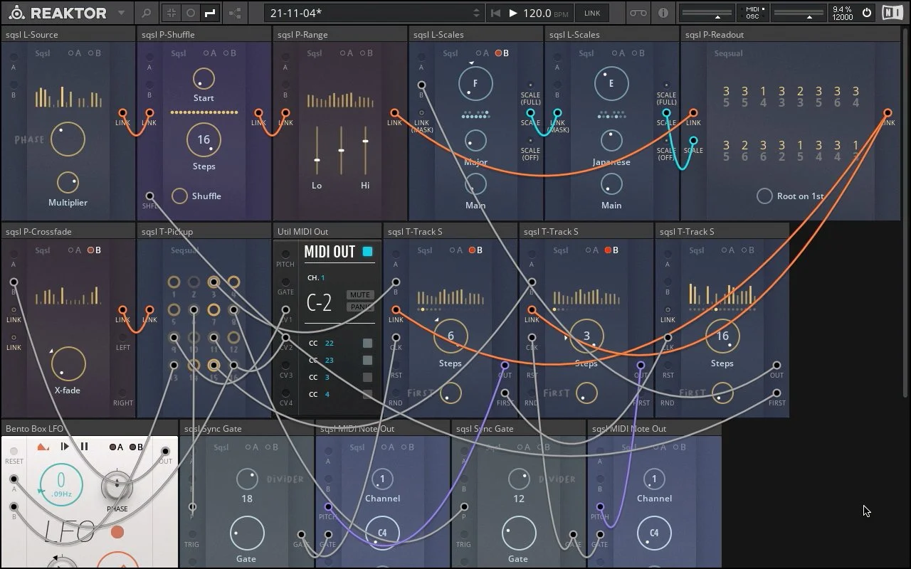
P-Crossfade (center left) allows smooth transitioning between two Link signals (upper LINK input = left, lower LINK input = right). If nothing is connected to its LINK inputs (as in this case), values for unconnected ports are being randomly generated when patch is loaded and regenerated when X-Fade control reach the respective extreme opposite position (left input is regenerated when control reach full right position and vice-a-versa).
–
In this patch, X-Fade control is being modulated by Bento Box LFO (B modulation input) resulting in P-Crossfade sending 16 channels of smoothly transitioning control signals through its LINK output. T-Pickup block is used to ”unpack” those morphing values from Link connection into regular modulation CV signals.
Signals 13 and 16 are used to Frequency and Shape parameter of Bento Box LFO, resulting in time variation of crossfade cycles.
Signals 9 and 11 are sent as MIDI CC streams (channel 22 and 23) through Util MIDI Out block and are modulating frequency/bandwidth of a band-pass filter in target VST instrument.
Signals 6 and 8 are used to generate note on/off messages. They are connected to P (pitch) inputs of two Sync Gate blocks (lower row) – gates are created and reset every time the received value changes after being internally quantized to chromatic scale (10 octave range – 120 values).
Signals 3 and 15 are modulating Steps parameters of two T-Tracks – changing their sequence lengths/loop points. Gate signals coming from Sync Gates mentioned above are advancing the active positions of both tracks.
First two T-Tracks are receiving their values from usual Source/Range/Readout chain placed in the first row. They output quantized picth values to MIDI Note Out blocks which are receiving same gate signals from Sync Gates mentioned above.
–
Third T-Track has nothing connected to its LINK input (values are generated randomly on load) and is being advanced every time the first T-Track reaches its initial position (trigger is sent from FIRST output to CLK input). Its purpose is to provide extra modulation for pitch values chain built in the first row by:
randomly re-ordering values in Link connection (trigger is sent from FIRST output to P-Shuffle’s SHFL input every time third T-Track loops);
modulating root note of masking scale – B input of left L-Scale.
Pitch value chain consist of L-Source, P-Shuffle, P-Range, P-Readout and two L-Scale blocks. L-Source is the origin of 16 values adjustable by only two parametric controls (Phase and Multiplier). Generated values are passed through Link connection to P-Shuffle that allows random re-ordering of values in Link signal. Next block in the chain – P-Range – is fiting the values within min/max range and sending them to P-Readout. P-Readout is displaying them numerically as octave/dergee in scale position and quantizing them according to signal received at its SCALE input. L-Scale on the right is acting as master scale (its SCALE output is connected to P-Readout) and left L-Scale is acting as masking scale (its output is connected to MASK input of master scale). Right scale is being masked by left scale – the intersection of both scales is used for quantizing (with master scale’s root note preserved).